|

Introdução
As portas lógicas são os componentes básicos da electrónica digital. Elas são usadas para criar circuitos digitais e até mesmo circuitos integrados complexos.
Por exemplo, circuitos integrados complexos podem ser um circuito digital completo pronto para serem usados – processadores e microcontroladores são os melhores exemplos –, mas internamente estes circuitos integrados foram projectados usando várias portas lógicas.
Nos parágrafos seguintes serão explicadas cada uma das portas lógicas e o seu funcionamento.
Como você já deve saber, em electrónica digital apenas dois números são permitidos, “0” e “1”.
Zero representa tensão de 0 V, enquanto que “1” representa uma tensão de 5 V (ou de 3,3 V no caso de circuitos integrados mais novos).
Você pode pensar nos números “0” e “1” como uma lâmpada sendo acesa ou apagada quando você liga ou desliga o seu interruptor.
Uma letra, também conhecida como variável, representa um número binário. Assim, “A” pode ser “0” ou “1”.
Se A estiver conectado a um interruptor, A será “0” quando o interruptor estiver desligado e “1” quando o interruptor estiver ligado.
Um traço sobre o nome da variável significa que o seu valor deve ser invertido. Por exemplo, se A = 0, /A será “1”, e se A = 1, /A será “0”.
Isto é o básico. Agora passemos às portas lógicas.
Inversor
Como o próprio nome já sugere, o inversor irá inverter o valor colocado na entrada.
Se você colocar na entrada de um circuito inversor o valor “0”, você obterá na saída o valor “1”, da mesma forma que se você colocar o valor “1” obterá “0” na saída.
A porta inversora é também conhecida como NOT e sua saída é Y = /A.
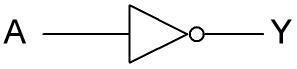
Figura 1: Inversor.
Na tabela verdade abaixo você pode ver um resumo de como este circuito funciona.
|
A (Entrada)
|
Y (Saída)
|
|
0
|
1
|
|
1
|
0
|
Em circuitos lógicos, usamos o símbolo “o” como forma abreviada para o inversor. Você verá este símbolo em portas lógicas do tipo NAND, NOR e XNOR.
AND
Como o nome já sugere, uma porta lógica AND realiza uma operação lógica “AND” (“E”), que é uma multiplicação.
Ela possui pelo menos duas entradas mas pode ter mais. Por isso, se A e B são suas entradas, na saída teremos o resultado de A x B (também representado como A · B).
A porta lógica AND pode ser resumida através da fórmula Y = A x B (ou Y = A · B).
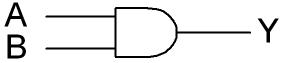
Figura 2: Porta lógica AND.
|
A
|
B
|
Y
|
|
0
|
0
|
0
|
|
0
|
1
|
0
|
|
1
|
0
|
0
|
|
1
|
1
|
1
|
Outras maneiras de entender a porta lógica AND:
-a sua saída será sempre “1” quando todos os valores de entrada forem também iguais a “1”. Caso isso não ocorra, o valor da sua saída será “0”.
-para a saída ser '1', têm que ser '1' as entradas A e B.
OR
Como o nome sugere, uma porta lógica OR realiza uma operação lógica “OR” (“OU”), que é uma adição.
Ela possui pelo menos duas entradas. Por isso, se A e B são suas entradas, na saída teremos o resultado de A + B.
Uma porta lógica OR pode ser resumida através da fórmula Y= A + B.
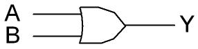
Figura 3: Porta lógica OR.
|
A
|
B
|
Y
|
|
0
|
0
|
0
|
|
0
|
1
|
1
|
|
1
|
0
|
1
|
|
1
|
1
|
1
|
Outras maneiras de entender a porta lógica OR:
-A sua saída será sempre “0” quando todos os valores de entrada forem iguais a “0”. Caso contrário, sua saída será “1”.
- A saída será '1' quando for '1' pelo menos uma das entradas.
|

Introduction
Logic gates are the basic components in digital electronics. They are used to create digital circuits and even complex integrated circuits. For example, complex integrated circuits may bring already a complete circuit ready to be used – microprocessors and microcontrollers are the best example – but inside them they were projected using several logic gates.
In this tutorial we will teach you everything you need to know about logic gates, with several examples.
As you may already know, digital electronics accept only two numbers, “0” and “1”. Zero means a 0 V voltage, while “1” means 5 V voltage or 3.3 V voltage on newer integrated circuits. You can think “0” and “1” as a light bulb turned off or on or as a switch turned off or on.
A letter, also known as variable, represents a binary number. So “A” can be “0” or “1”. So, if A is connected to a switch, A will be “0” when the switch is turned off and “1” when the switch is turned on.
A line drawn right above the variable name means that the variable is inverted. For example, if A = 0, /A will be “1”, and if A = 1, /A will be “0”.
Now that you know the basics, we can introduce you to logic gates.
Inverter
As the name implies, inverter will invert the number entered.
If you enter “0”, you will get a “1” on its output, and if you enter a “1”, you will get a “0” on its output.
The inverter symbol you can see on Figure 1. Inverter gate is also known as NOT and its output is Y = /A.
Figure 1: Inverter.
On the truth table below you can see a summary of how this circuit works.
|
A (Input)
|
Y (Output)
|
|
0
|
1
|
|
1
|
0
|
On logic circuits, a “o” symbol is a short for inverter. You will see that on logic gates like NAND, NOR and XNOR.
AND
As its name implies, an AND logic gate performs an “AND” logic operation, which is a multiplication.
It has at least two inputs. So, if A and B are its inputs, at the output we will find A x B (also represented as A · B).
So, AND logic gate can be summarized by the formula Y = A x B (or Y = A · B).
Figure 2: AND logic gate.
|
A
|
B
|
Y
|
|
0
|
0
|
0
|
|
0
|
1
|
0
|
|
1
|
0
|
0
|
|
1
|
1
|
1
|
Another way to understand AND logic gate:
- its output will only be at “1” when all its inputs are also at “1”. Otherwise its output will be “0”.
- to have '1' in the output, you must have '1' in the inputs A and B .
OR
As its name implies, an OR logic gate performs an “OR” logic operation, which is an addition.
It has at least two inputs. So, if A and B are its inputs, at the output we will find A + B.
So, OR logic gate can be summarized by the formula Y = A + B. You can see its symbol on Figure 10 and its truth table right below it.
Figure 3: OR logic gate.
|
A
|
B
|
Y
|
|
0
|
0
|
0
|
|
0
|
1
|
1
|
|
1
|
0
|
1
|
|
1
|
1
|
1
|
Another way to understand OR logic gate:
-its output will only be at “0” when all its inputs are also at “0”. Otherwise its output will be “1”.
-the output will be '1' when you have '1' at least in one input.
|